Arduino soil moisture sensor
I have a few friends interested in automated farming so when I ordered my latest batch of components I added a SparkFun soil moisture sensor to my order. Here is what I learned while setting it up and getting my first reading.
Connecting the sensor
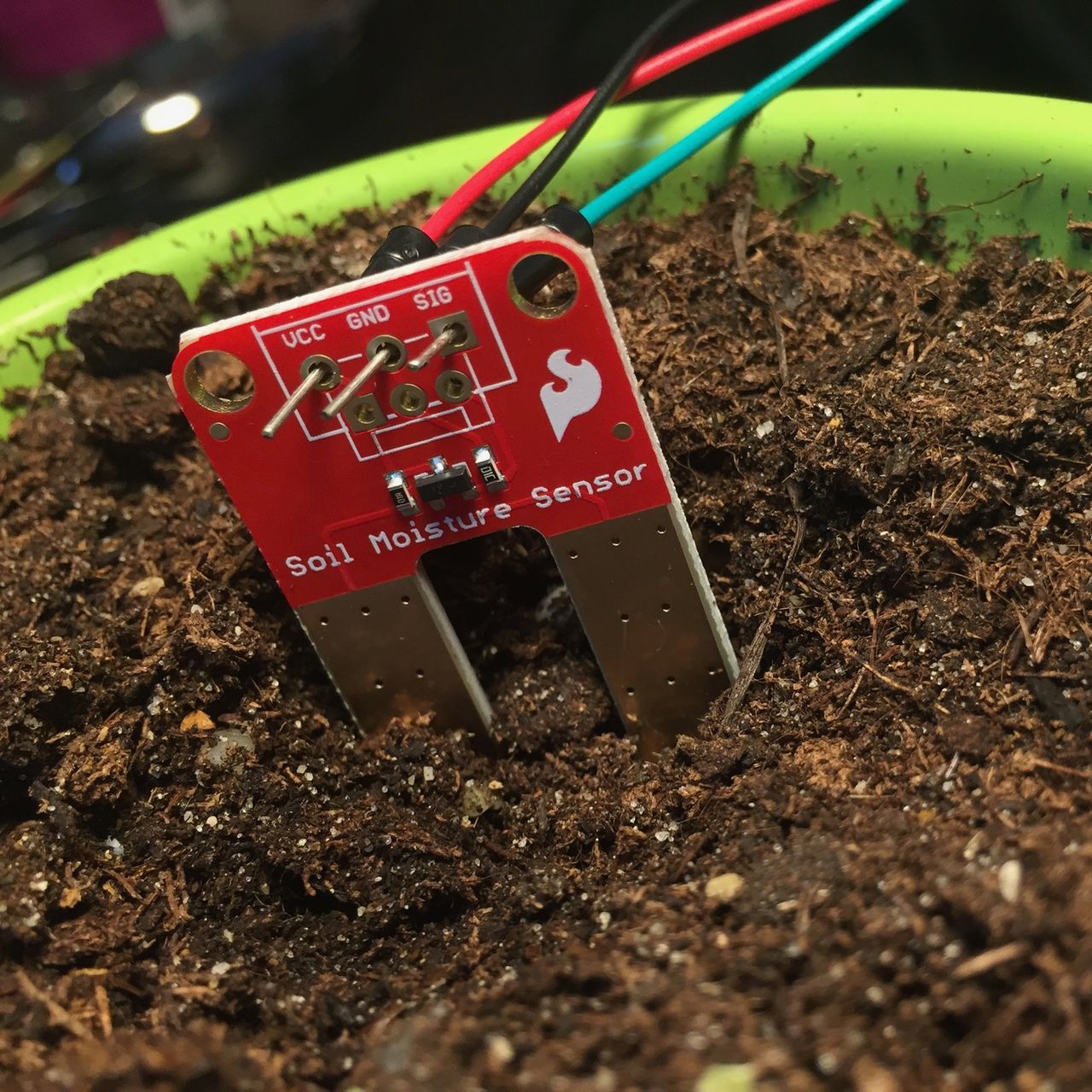
I got my breakout board from SparkFun. They have nice embedded sensors that significantly reduce the work needed to get up and running. This breakout has three connections: VCC, GND, and SIG.
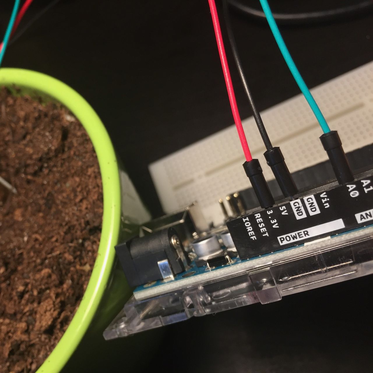
VCC is the positive power terminal. The sensor can accept both 3.3V and 5V power input. So any pin on the Arduino will be suitable as a power source. I used the 3.3V power pin to get started.
GND is the negative power terminal. Look for GND on the Arduino, or alternatively you can set any pin as a negative terminal.
SIG is the moisture reading. The sensor outputs a signal based on two main factors: the input voltage and the moisture level of the soil. It should be hooked up to an analog pin in order to read the signal properly. In my photos and code samples I used analog A0 pin to read the signal.
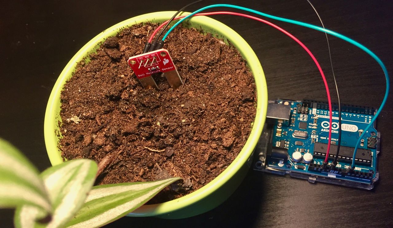
Once everything is connected you are ready to program the Arduino!
Talking to plants
The code to get a reading is delightfully simple. Just initialize the A0 pin as an input then do an analogRead() to monitor the signal. Opening the Arduino IDE serial plotter will show you a real-time reading of your soil moisture.
const int soil = A0;

void setup() {
  pinMode(soil, INPUT);

  // initialize serial plotter
  Serial.begin(9600);
}

void loop() {
  // read value and send to plotter
  Serial.println(analogRead(soil));

  delay(50);
}
If you want to change the frequency of readings, adjust the delay() time.
One cool surprise: while looking at the plotter, I touched the plant and the signal changed. My body's electricity flowed through the plant, the dirt, and also the sensor! I definitely did not expect that to happen so it was fun to play around with the plotter signal to confirm that it was really happening.
Adapting code for long-term use
The way this sensor is normally used, it's left embedded and a reading is taken every so often, e.g. once an hour. Powering the Arduino long-term is no problem, but the docs for this sensor (PDF, 98KB) recommend that you only send power to the sensor when actively taking a reading of the soil moisture. Powering only during these short moments helps avoid corrosion caused by the constant flow of electricity between the two pads of the sensor.
To control whether the sensor receives power, you'll need to avoid using the 3.3V or 5V pins. Instead use a digital pin for power. Using a digital pin allows you to send temporary bursts of power to the sensor by controlling it in code. I moved my positive wire from the 3.3V power pin to digital 12 pin.
Here is a new program which takes a reading once every minute. Change the TIMER variable to control the number of seconds between readings.
// Define our pins.
const int soil = A0;
const int power = 12;

// Define our timer.
const int TIMER = 60; // in seconds
const int RESET = TIMER - 1;
const int SENSOR_DELAY = 10; // in milliseconds
int counter;


void setup() {
  pinMode(soil, INPUT);
  pinMode(power, OUTPUT);

  // Start with sensor OFF
  digitalWrite(power, LOW);

  // Setup timer.
  counter = RESET;

  // Setup serial plotter.
  Serial.begin(9600);
}


void loop() {
  // If the counter is at the end of a cycle
  // take a new reading and reset counter.
  if (counter <= 0) {
    // Turn sensor ON and wait a moment.
    digitalWrite(power, HIGH);
    delay(SENSOR_DELAY);

    // Take reading, send to plotter.
    Serial.println(analogRead(soil));

    // Turn sensor OFF again.
    digitalWrite(power, LOW);

    // Start new countdown.
    counter = RESET;
  }

  // If counter isn't at the end yet, pause for
  // the same amount of time as if the sensor
  // had been activated to keep things in sync.
  else {
    delay(SENSOR_DELAY);
  }

  // Decrement counter and delay until next second.
  counter--;
  delay(1000 - SENSOR_DELAY);
}
The main program loop has a counter that starts at 59 and counts down to 0. When it reaches 0, it takes a reading and resets the counter. By only powering the moisture sensor for 10 milliseconds out of every minute, we are significantly delaying corrosion caused by excessive current.
Run the program, open the Arduino IDE serial plotter, and go make yourself a tea. After a few minutes you should have your first few readings!
Reading logs
Once you are taking readings, it's important to figure out what the bounds for your plant are. Using 3.3V power here are some readings I measured over the course of a few days. The SparkFun sensor outputs a 10-bit signal meaning 1023 is the upper limit:
- 0-45 — completely dry soil
- 890 — immediately after watering dry soil
- 875 — second day
- 872 — third day
- 823 — fourth day
- 460 — fifth day
This sharp drop on the last day indicates to me that most of the soil surrounding my sensor is pretty dry. There is probably some moisture near the bottom of the pot, but if the sensor is pushed deeply enough into the dirt, then it's a good indication that the plant actually needs some water.
I noticed that my sensor gives very reliable readings in the 800 range, but has some rather wide oscillations as the moisture drops. I couldn't find a reason online that helped me resolve the problem. It could be my connections, the intervals that I'm taking the data, or something I haven't even heard of yet. Regardless, if you see some oscillation in the data, try using input smoothing.
While looking into reference data for soil moisture, I found an incredible collection of data provided by SparkFun. It is an open database that you can participate in! I found a few streams of data related to soil moisture, but since they are user-generated there's no guarantee they'll persist if I link to them. Just use the site's search and find one.
Building on this sensor
After getting your first successful reading, the next step is to display the data somehow. This could be an LED display, saved to a data logger, sending notifications to your phone, or even a self-watering system that dispenses a few drops of water when the plant is in need of a drink. The sky's really the limit so use your imagination!
Webmentions
Have you linked to this page from your site? Submit your URL and it will appear below. Learn more.
Mentioned by
Building an automated greenhouse with Arduino
My friend Afra invited me to participate in a conference in Sweden involving sustainable urban greenhouse solutions. Så Ett Frö (Plant a Seed) is a collaboration with HSB Living Lab, a 10-year-long experiment which uses technology to help build more sustainable housing building.
My job was to automate a small greenhouse using my budding Arduino skills. The main objective of Så Ett Frö is education amongst grades 7-9. So for now we haven't spent time calculating economic value or carbon footprint. Future iterations will hopefully allow us to tackle these engineering issues which will make the greenhouse more sustainable.
Building the frame
We know our strengths and working with wood wasn't one of them. Luckily Afra has a friend who is quite talented working with wood, so in an afternoon while we debugged the LCD, he was building the frame of our greenhouse. He used scrap wood from HSB Living Lab, and some used plexiglass that Afra obtained from the city that would have been thrown away.
In the end it was approximately 80x60x80 centimeters, roughly the shape of a classic PC tower. One of the small sides has a hinged door and all other entry points were created by drilling holes in either the plastic or notches in the wood.
Arduino components
We used the following sensors to collect data from the greenhouse:
We planned to use the following components to control the environment in the greenhouse:
- Arduino Uno R3
- Peristaltic water pump
- LED lamps
- Ventilation fan
- Photosensor (future)
- Real-time clock module (future)
- Solar panels (future)
- LCD for real-time data reporting
Arduino is the center of the automation system. It receives all the sensor data and responds by controlling most of the components.
The water pump provides plants with water. The watering is triggered by the soil moisture sensor, which can detect when the soil has become too dry. The pump can be quite small, and only has to run for very short periods of time to provide water to the plants. Unfortunately even a small pump requires an external power supply, because the Arduino can't handle the load of the motor when converted from 5V to 12V.
The LED lamps provide a supplement to sunlight energy. Of course, if there's sunlight available then it's preferential, but LED lamps can help out when the sun isn't shining as many hours during winter in places up north like Sweden. Ideally, we would use photosensors to detect light conditions instead of relying on timed schedules, but in cases where we only detect a few hours of light per day, the real-time clock can help guide the Arduino to turn LED lamps on for a few extra hours to hit a target light cycle.
Ventilation fans help regulate air temperature and humidity. Plants need air with CO2 to grow properly, and their "waste" is good for humans to breathe. So it's nice to stir up the air every once in a while. This is something that could possibly be handled by enclosure design rather than a fan, reducing the energy footprint. But for our prototype, we included the fan since it was a simple solution.
Real-time clock module helps keep regular schedules. Arduinos cannot reliably keep time, so a small module with its own coin battery helps provide some continuity in cases where the Arduino momentarily loses power or receives code updates necessitating a reboot. We didn't include the clock in our prototype this time, but it's good to keep in mind for the future.
Solar panels would ideally power the entire system. Ensuring that the greenhouse is not using grid energy is one of the most important goals of creating a sustainable solution. If the system requires more energy than a reasonably sized solar panel the responsible solution is to reduce our energy consumption, rather than increase panel size. A battery would be required as well, but we haven't made any progress on integrating the panel yet, so this is a problem we'll tackle in the future.
An LCD allows someone to check conditions of the greenhouse. While technically optional, it allows a novice grower to check on conditions and determine if changes need to be made to the system. It was also an appealing interactive component to our prototype since it was on display at a public event.
Building manual
Now in its second year, Så Ett Frö is accumulating knowledge by requiring that a manual be written once students are done building. The sharing of knowledge is the actual seed being planted!
Here's the manual from the first year (the website has been taken down), which includes detailed parts lists and instructions for how to build the entire structure.